全部
  • 全部
  • 产品管理
  • 新闻资讯
  • 介绍内容
  • 企业网点
  • 常见问题
  • 企业视频
  • 企业图册

/ NORRES / 工程

Length Cutting and Assembly Information

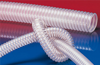
Cutting of spirally reinforced plastic hoses

Step 1: Rip the hose open, preferably with a ragged knife.
Step 2: Intersect the supporting spiral with pliers.

Cutting of the metal hoses 375 – 377

Step 1: Fix the ends with rivets or by soldering.
Step 2: Lever out the profile with a screw driver.
Step 3: Cutting of the protruding profile with a shear blade or diagonal cutting pliers.

Grounding for protection against electrostatic charging

The correct and continuous grounding of all installation components (including hoses and with hose ends connected accessories) largely protects against process troubles and ignition of explosive atmospheres. Please note our corresponding data sheet electrostatic charging.

Grounding Variant 1: Expose the spiral, bend it to the inside and mount it onto a conductive socket.
Variant 1: Expose the spiral, bend it to the inside and mount it onto a conductive socket.
Grounding Variant 2: Expose the spiral and fix it, for example, by a rivet or screw.
Variant 2: Expose the spiral and fix it, for example, by a rivet or screw.

Strip insulation of AIRDUC® hoses

Step 1: Cut hose with a fine-toothed knife along the steel wire.
Step 2: Either pull off plastic piece with a piece wire stripper...
...or remove it more convenient with a special dismantle tongs.

Sufficient tightness by assembling

A sufficient tightness can in the main only be achieved by our own developed spiral hose clamps. Emerging media can endanger man and environment, trouble the process and often impair the efficiency of an application.

Tight assembly by the use of the original accessories.
Significant leakage by the use of conventional hose clamps.

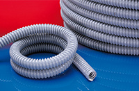
Cutting of bare or plastic coated cable protection hoses of metal (types 101 – 109)

By bending:

Step 1: Cut the plastic mantle (if existing).
Step 2: Bend the metal hose.
Step 3: Cutting of the protruding profile with a shear blade or diagonal cutting pliers.

By intersecting:

Step 1: Cut the plastic mantle (if existing).
Step 2: Intersect axially with a small carbide-tipped saw blade.
Step 3: Separate the ends from each other by turning apart.

By sawing:

Cut the metal hose on a belt saw at high cutting speed.

NORDUC® one hand assembly system

Due to the conic inside and the snap in hooks, the connector is universal suitable for different tube profiles. (Standard-, Coarse- and UFW-profile) IP 65 is reached acc. to EN 60529/IEC 60529 in this combination. The IP 68 rate is attained with an O-ring sealing, mounted in the first wave trough of the tube (trade size 50 in the first and second groove).

Step 1: Separate the tube at a corrugation crest (optimal protection of the tube and connector).
Step 2: Insert the tube into the „closed“ connector as far as it will go (to assemble the connector).
Step 3: Pull the corrugated tube back slightly inside the connector (to latch securely).
Step 4: Move the detent lugs out (to dismantle the connector).
Step 5: Pull the corrugated tube out of the connector.
Step 6: Push the detent lugs in (NORDUC® assembly system ready to use again).

Engineering modifications subject to change.